I always enjoyed building model rockets with my dad and sister as a kid but always found the construction process of cutting, sanding, aligning, and gluing the balsa wood fins to be tedious and take a lot of fun out of the process. Back then the hot glue gun fixed a number of model rocket fabrication shortcomings for me.
Paper Towel Roll Concept
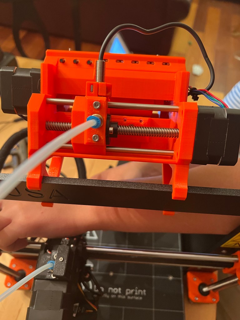
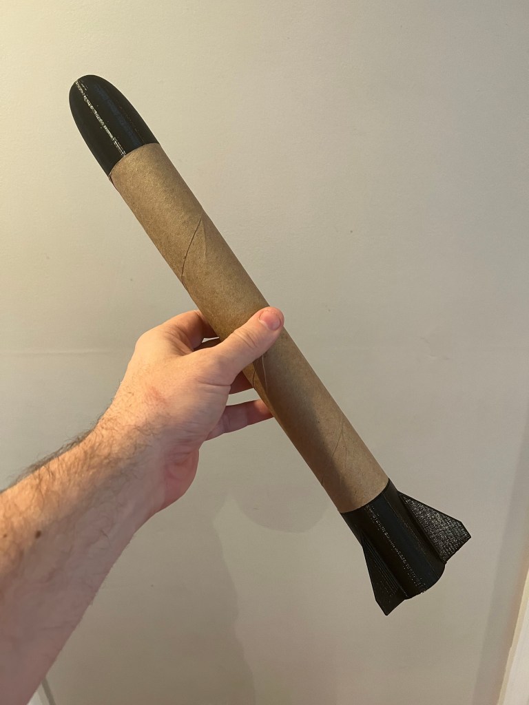
For a good while now every time I see an empty paper towel roll I see a model rocket body. I’ve been mulling a concept in my head for some time now to design and 3D print a model rocket nose cone and model rocket fins that could attach seamlessly to a paper towel roll to serve as the model rocket body. We had some empty bounty paper towels in the house so this weekend we fired up the CAD and the 3D printer and gave it a shot. The final results came out better than I could have expected!


Verdict
It works! Our only problem was that we only had wimpy “A” rated model rocket engines on hand. Due to the weight of the assembly combined with the underpowered rocket engine the first two 3D. Printer paper towel roll prototypes went less than 100 feet into the air. Other than that everything worked splendidly.
Next Iteration
My goal for the next iteration is to take the design down to the minimum 3d printer wall thickness (the internet is telling me the minimum is about 1.5 to 0.8 mm for the absolute minimum) and see how well the structural integrity of the design holds up. That combined with some “C” rated model engines should add some serious kick to our rocket power of these 3D printed “bounty towel” rockets. This isn’t rocket science (or is it?)