I designed and 3d printed a custom LED fidget box toy (shown above) for my nieces and nephews to play with when they visit. In a world of omnipresent screens there is something very tactile and extremely satisfying to toggle a switch on and off. The design is a shrunken and optimized version of the toggle boxes I previously made for the 2022 Philly Makerfaire. It’s a simple series circuit that runs off a 9V battery. The challenge comes with wiring and subsequently packing all the wiring and the battery into a very small enclosure. I decided it was time to try my hand at ordering a custom printed circuit board (PCB) that would make the assembly easier.
DIY PCB
After some cost comparison research I decided to order the custom PCB from JLCPCB. Anthropic’s Claude code linked to my Autodesk Fusion CAD software helped me layout the PCB board size to fit exactly into the enclosure of the fidget box. Claude Code also helped walk me through the ordering steps. I clicked purchase and two weeks later the PCBs magically arrived in the mail.
The custom PCB works!
Packing the PCB, battery and wires into the enclosure still makes for a very tight fit, but the setup and wiring was a breeze this time around with the PCB serving as the backbone of the fidget box toy. The next challenge is to machine a full enclosure for one of these out of shiny aluminum on my Tormach CNC machine. This is not a complex device, but this little experiment serves as an encouraging evolution step towards making more complex devices that run off PCBs integrated with a microprocessor and other electronic components that integrate and combine tactile switches with user feedback.
Amateur radio is a hobby about distance. You sit in a room with a wire in the air, you say your callsign into the noise, and sometimes a stranger seven thousand kilometers away says it back. That is the entire magic trick, and it has not gotten old in a hundred years.
The strange part is that logging that moment, the thing every operator does after every contact, is almost universally a spreadsheet. A row. Callsign, frequency, time, signal report. The most romantic hobby in the world, recorded like an invoice.
So that is the app: QSO Globe. You log a contact in one line, and a golden arc launches from your station and lands on theirs, across a 3D globe that shows the real day and night, with the greyline creeping across the planet exactly where it actually is right now.
Log a contact and watch the arc fly. The terminator is real and moving.
The Greyline Is Not Decoration
Here is the part that made me want to build it. The greyline, that band of twilight between day and night, is not just pretty. It is a genuine propagation phenomenon. Along that line, the ionosphere’s absorbing layer is fading out while the reflecting layer is still up, and signals can travel absurd distances for a little while. Old-timers have chased it forever: get on twenty meters at your sunrise, point at someone else’s sunset, and work the world on the power of a light bulb.
Almost no logger shows you this. You are supposed to keep it in your head, or check a separate propagation site, and then go back to your spreadsheet.
If the globe already knows where the sun is, and it has to in order to draw the planet honestly, then it can show you the greyline for free. The feature that would be a whole product somewhere else is a side effect of drawing the earth correctly.
Scratching My Own Itch
If you have read the earlier posts in this series, you know the setup: I am not a programmer. I build these by describing what I want to Anthropic’s Claude Code and iterating stubbornly until the thing exists.
This one exists for a simple reason: it is the logger I wished I owned. I wanted to see my operating from a global perspective — not a spreadsheet row that says “Japan,” but an arc leaving my backyard and landing on the other side of the planet, on a globe that shows day and night where they actually are right now. Radio is a hobby about distance, and I wanted the log to feel like the distance.
And I wanted it to work off the grid. Parks on the Air activations happen precisely where there is no signal — so the app carries an offline country file, needs no account and no server, and keeps the entire log on the phone. A logger that only works with bars of LTE fails at the exact moment the hobby gets good.
So the feature list was never a roadmap. It was a wish list, written by the operator who has to live with it.
The Real Work Was the Conventions
The recurring lesson of this series is that the code is the fast part and something else is the real work. For the weather app it was personality. For the math app it was curriculum. For the bedtime app it was sound.
For a ham radio logger, it is a hundred years of conventions that the computer does not know and cannot guess.
Signal reports are two or three digits and the digits mean specific things. Times are UTC, always, no exceptions, because the hobby is global and local time is a parochial fiction. Duplicate contacts are not simply repeats. For Parks on the Air, a dupe means the same callsign on the same band and mode within the same UTC day, and that definition is load-bearing for whether an activation counts. ADIF, the log interchange format, is older than most of the people using it and has to round-trip exactly or you cannot upload to Logbook of the World.
None of that is hard to implement once you know it. All of it is invisible if you do not, and every single piece of it is the difference between a logger a ham will actually use and a pretty toy that gets deleted in ninety seconds. You cannot vibe-code your way to domain knowledge. You have to either have it or go get it.
One line in, one contact logged. W1AW 14.243 57 55 is enough.
What It Actually Does
Log a contact by typing it the way you would say it: free-order tokens, callsign first, the rest optional. Tap a band chip and the frequency prefills. Signal reports default to the ones you were going to type anyway.
For Parks on the Air, activation mode makes your park the origin of every arc, live spots show up as pins you can tap to prefill the log bar, and park-to-park contacts resolve to the actual park. ADIF imports and exports round-trip the POTA fields properly. There is an offline country file so the app still knows where a prefix lives when you are somewhere with no signal, which is precisely where activations happen.
At the end of a session you can replay it, arc by arc, and generate a share card that only claims what you actually did. It says four countries on two continents when you worked four countries on two continents, and not otherwise.
No account. No tracking. Free.
The share card tells the truth, or it says nothing.
The Honest Gaps
Version 1.0 is iPhone-only. The globe needs verifying on real iPad hardware before I claim it works there.
Logbook of the World is export-only. You export and upload with TQSL like always; I have not built a signing integration. QRZ and eQSL push work, but with your own credentials, because I am not going to be a middleman for anybody’s logbook.
And it has not yet been beaten up by strangers. It has been tested by exactly one operator, me, which is one more than zero and far fewer than it needs.
The Wait
Then Apple reviewed it, and for a good while nothing at all seemed to be happening — which is exactly what is happening inside a review queue, because queues are unordered.
The lesson from earlier rounds still holds. App Review is a conversation, not a verdict. But this round taught a duller companion lesson. Sometimes it is not a conversation. Sometimes it is just a wait, and the only correct move is to go build the next thing and let the clock run.
It is approved now. It is on the App Store, it is free, and it is on my phone in the shack where it belongs. For a logger, that is the only review that was ever going to matter.
If you are a ham and you take it out on an activation, I would genuinely value the punch list. That is not a marketing line: v1.0 is one operator’s opinion about what a logger should be, and the only way that becomes right is other operators telling me where it is wrong.
I’m pivoting over to CAD modeling and 3d printing storage bases to store the chucks for my Grizzly G4003 lathe when not in use. the concept was something with holes to accept the dowel pins face down and side grips to easily grab and lift the lathe chuck into and out of the tool chest. Simple right?
5C Collet Chuck Base Concept modeled with Autodesk Fusion 360Slicing up the 3d model with Prusa Slicer software3D printing the 5C collet chuck base with the Prusia 3d printer 3D printed Collet Chuck Base – the finished print 5C Collet Chuck prototype – proof of concept
The first concept came out better than I had hoped but I see a few areas for improvement. The next interaction I am going to increase the diameter of the dowel holes to make landing the chuck ridiculously easy and to make the side grips wider and longer to it’s less tippy in your hands.
I recently upgraded my precision measuring instrument (PMI) toolbox with a lovely Mitutoyo vernier caliper and a Mitutoyo micrometer. They are sweet! Buttery smooth precision.
My new Mitutoyo MicrometerMy Mitutoyo Vernier Caliper
That being said, I still have an economy Pittsburg Tools vernier caliper acquired from Harbor Freight that has served me well in years past. Especially when you consider it retails for under $20.
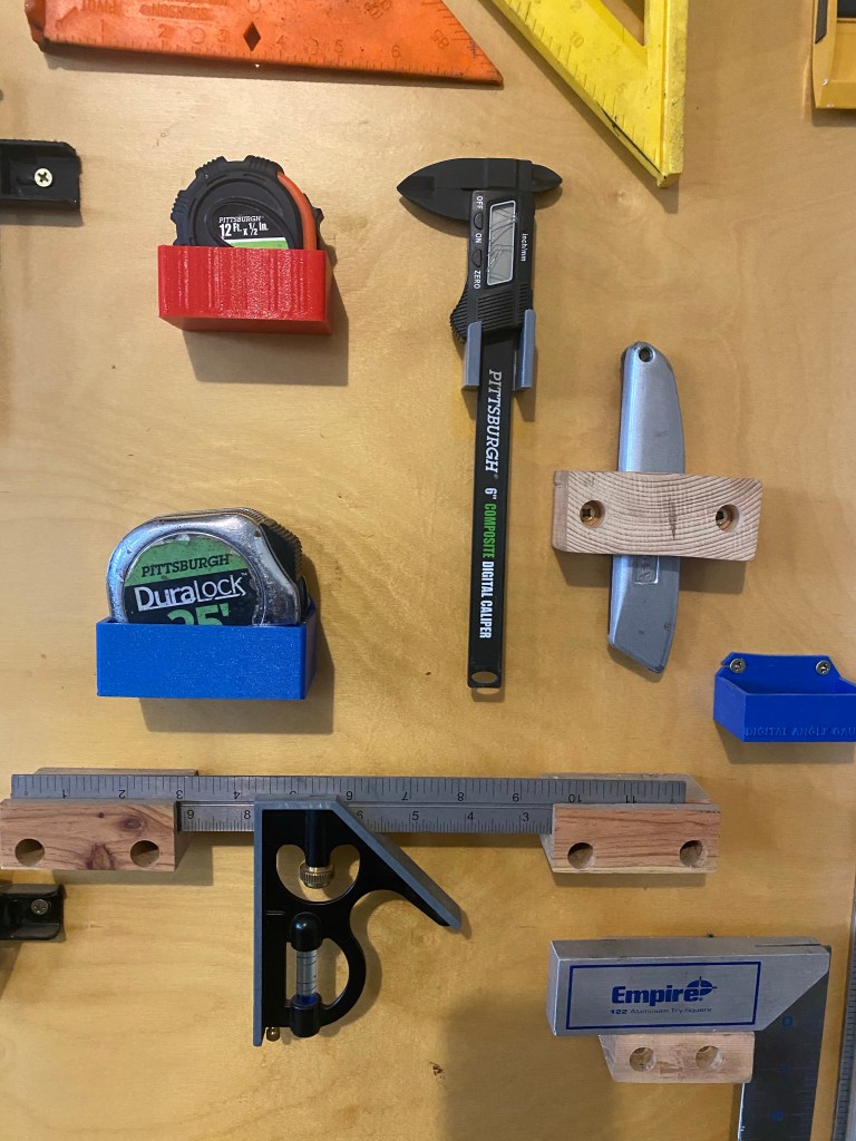
I still like to keep the Pittsburg caliper on my tool wall for quick and dirty measurements that don’t require three decimal place precision. I decided to model up a bracket for 3d printing to mount it on the tool wall.
Pittsburg Vernier Caliper tool wall mounting bracket 3d model
It took me three iterations to get the model right. The first prototype my mouthing angle for the angled base was off by a few degrees and the upper mounting arms were to thin and aesthetically too flimsy in my opinion.
The second iteration I was able to both add and remove material in various locations to optimize the print time down to 40 minutes.
The pandemic has allowed me the luxury of more time to pour over some of my machinist books. While reading Machine Shop Know How – The Tips and techniques of master machinists, I came across a very enticing project to make a dedicated center drill holder for my lathe tail stock.
Machine Shop Know – How by Frank Marlow
I started with a 3MT To 2JT Tanged End Drill Chuck Arbor purchased from Amazon for about $12.
Prepping the MT Jig
The center drill I selected to be used in the dedicated Morse taper fixture measured in at 0.248. I put the jig in the tail stock and used my relatively new collet chuck to center drill the jig with the collet holding the tool piece. Next the jig was drilled on the JT end just undersized and then finally finished out with a reamer. Again both operations were performed with the collet holding the tool pieces. I had to purchase a custom reamer for this and made the error of buying an exact fix reamer (0.248) which made the fit too tight for the first fit up. (Facepalm). I then ordered a reamer .001 larger (0.249) which after being reamed fit perfectly into the Jacobs taper end of the fixture.
3 Morse Taper to 2 Jacobs Taper Drill Chuck Arbor Drilling the MT to JT fixture to accept the center drillFinal reaming of the MT to JT fixture to accept the center drill
Adding a set screw
The text states to grind a flat on the center drill bit that will be used to accept the flat of a future set screw. This is best done on the surface grinder since the bit is hardened.
After the center drill holder was properly reamed to accept the center drill tool bit I drilled and tapped the Jacobs taper to accept a #10-24 set screw.
Drilling the MT to JT fixture to tap and add a set screwThe MT to JT fixture successfully tapped to hold a #10-24 set scew to secure the center drill in place.A dedicated MT center drill holder
The finished product came out well! I slapped the dedicated MT center drill into the tail stock and put a center indentation in a piece of scrap stock. The center bit did move a little more inwards before fully settling and bottoming into the reamed out hole and the set screw subsequently had to be lightly retightened. Otherwise all was well.
It works!
This is a simple tool but one that will add efficiency to the shop. This will be a pleasant addition to my lathe toolset.
Bostar 5C Collet Chuck on my Grizzly G4003 with a D1-4 base
My 3 Jaw Chuck Dilemma
After installing the new Digital Read Out (DRO) on my Grizzly 4003 lathe and doing some comparison cuts with the DRO and two micrometers I was made very aware that the preexisting 3-Jaw chuck could do no better than .005″ Total Indicated Runout (TIR) on the lathe. I was craving the ability to get faster more repeatable precision.
This desire for greater precision combined with recently seeing a few random collet chuck videos on YouTube spurred me to desire an entry level 5C collet chuck.
Ebay to the Rescue: Bostar 5C Collet Chuck
I finally settled upon a Bostar 5C Collet Chuck with D1-4 cam lock spindle mount purchased on EBAY for $139. The collet chuck was promplty shipped and arrived in less than a week.
Prepping the BOSTAR 5C collet chuck for installation Checking the total indicated runout (TIR) of the newly installed 5C collet chuck
I found the installation to be relatively straightforward and easy. The old 3 Jaw chuck did need a few taps with my trusty orange dead blow hammer to nudge it lose to get it off. The Bostar 5C Collet chuck went on and I was able to get it to under .001″ run-out in just a few minutes. Success!
Now it is time to do some machining with this thing!
I purchased a Taishi 2 Axis Digital Read Out with precision linear scales for my Grizzly Lathe G4003. The DRO was $265 which seems like a good deal, especially when you compare the price to the Grizzly brand DROs that retail between $700 and $800!
The DRO unboxed
Taishi 2 Axis Precision Linear Scale DROTaishi 2 Axis precision linear scales for my Grizzly G4003GC8900-2D DRO
DRO Scale Dimensions
After I ordered the DRO from amazon.com. I got a message from the vendor ( asking me for X axis and Y axis dimensions. For the Grizzly G4003 I sent them dimensions 6.76” x 30.75” (175 mm x 785mm). The DRO was shipped from Guangzhou, China and arrived on my doorstep remarkably in a little over a week. (If I did this over ever again I would add a quarter inch to the size of each scale to ensure the scale is never the limiting factor in axis travel.)
DRO X axis
The DRO came with a manual on how to operate the DRO screen, but there were no installation instructions. Buried in the Amazon reviews was a recommendation for watching a YouTube clip by DROPros which I did watch and found very instructive and useful.
The DRO pros video recommended using double sided tape to test drive the setup. I purchased the exact type (3M double sided outdoor tape) but I found the tape to not be strong enough to work in my case. Perhaps if I had wiped down the surfaces more or let the tape set longer it would have worked, regardless it didn’t work in my case and I abandoned the double sided tape fit up attempt.
The Scotch outdoor mounting tape didn’t work for me for the dry fitup of the DRO
3D Printed Shim
There was a 0.08 overhang where the fixed sensor head was going to be placed. I decided to quickly model shim to the exact dimensions required and printed it to take up the gap. Entire print time of this shim? 9 minutes! Sweet!
A 3d printed shim for my G4003 Grizzly Lathe DROA 3d printed shim to take up the gap on my Grizzly G4003 lathe cross slide
Time to drill and tap!
The DRO shipped with variou lengths of 4mm – 0.7 screws. I drilled the linear scale fastener hole closest to me with a 3.5mm drill bit first and then tapped this hole. This was also my first opportunity to use my drill and tap straight-alignment guide fixtures. (I bought these at Cabin Fever Expo 2020). I used a transfer punch to set the location in the middle of the slotted hole on the linear scale end.
The Big Gator Tools tap guide I purchased at the 2020 Cabin Fever Expo ensured my threading was straight and perpendicular. It exceeded my expectations. Tapping the lathe cross slide for the X axis DRO The DRO scale was installed the the cable routing solution was not ideal
I did each step very iteratively. After drilling and tapping the first hole I re fit up the scale and then punched the second hole. I drilled and tapped that and then after successfully mounting both of the holes for the scale I did each home for the sliding sensor one at a time as well. Take your time and iterate.
My DRO Dilemma- cable routing
After I mounted the X axis scale I discovered a new dilemma; the cable routing up and over the saddle was highly unsatisfactory to me. Searching for answers I stumbled across an internet post where someone was recommending you mill a small slot and route the cable straight through and under the slide itself. Initially I scoffed at this idea but later came to realize this was the only workable solution. This was going to require some serious disassembly on my Grizzly G4003 lathe!
Removing the Grizzly G4003 Saddle
WARNING: Getting the saddle off is a major pain on the rear! the rear ways weren’t too hard to get off but there were 2 fasteners on the front side that I simply could not reach with my wrench. Perhaps there is an alternate way to get these Seriously hard to access fasteners off is unknown to me, if I had to do this again I would write Grizzly for advice. Ultimately I had to loosen the upper saddle cap screws and then slip a hack saw into the slit between the upper and lower components to cut the 2 roll pins connecting it to the base so I could shift and slide the upper part of the saddle left or right to get to the final inner way fasteners. I was extremely displeased at the end of this because I accidentally nicked my cross slide wheel with the hacksaw when cutting the roll pins. My lathe is going to have some battle scars after the installation of the DRO
Milling my Grizzly lathe saddle in my Bridgeport milking machine
Milling a slot
Milling a slot in the saddle with a round nose endmillThe DRO cable can now route directly under the linear scale to the back of the lathe. Success!!!DRO cable routed through a slot milled in the saddle
Y Axis
For the Y axis I mounted the scale directly to the bed. It should be noted the bed is a casting so it has a slight draft angle. I used a single washer as a spacer and a carpenter level for the initial layout. I milled a flat bracket 1/4” piece that could screw directly into the prexisting chip cover holes and put vertical slots in the bottom to fit up the sensor. I 3d printed a slotted block to take up the gap between the plate and the sensor. I put a matching angle in the slotted 3d block.
My understanding is the G4003 and G4003g are very similar in form, fit, and function. The G4003G is the gunsmith model and has a few more upscale features, but it is my assumption the concepts presented here should work on the G4003g model as well.
Did I mention I hate pegboard? I hate it, flimsy and ugly! I’m on a mission to custom print every tool holder for my custom made tool wall that is finishing out nicely. After making a socket holder, I decided it was time to make some holders for my disorganized socket sets. I made one set of shallow holders for metric and one for SAE for my 3/8 drive socket wrench.
I’m trying to decide if I like having the letters in an engraved or embossed format.
Next up I’m going to design and print one for my deep socket set. after that is done I’ll make a set for my 1/4 and 1/2 socket sets.
Socket wrench tool holder3d printed socket head ratchet holder on Prusa i3Mk3s
Tonight I finally scratched a big itch of mine to design a quick lift and go tool holder for my drive ratchet set. I had a good idea in my head how I wanted it to work. It didn’t take too long to model it. I was very pleased with my first prototype. The color of the bright metallic blue of this ProtoPasta filament I’ve recently switched over to looks brilliant and is remarkably sturdy. I NEED to try some of the Neon yellow of this type of filament!!!