
A DIY 3D Printed Rocket Launcher
After successfully launching a multitude of my 3D printed Bounty Towel rockets, my kids and I decided we needed a more badass rocket launcher than the bland and generic store bought mass manufactured versions. My biggest complaint with the generic store bought models is when you press the switch you get very little feedback on what is happening. This is especially concerning when the rocket doesn’t immediately launch. There is also ample opportunity for improvement in the aesthetics department on these devices.
This project was featured on Hackaday, in their coverage of the Philadelphia Maker Faire.
If we wanted an awesome rocket launcher we were going to have to print, build, wire, and assemble it ourselves!
Model Rocket Launcher Plans
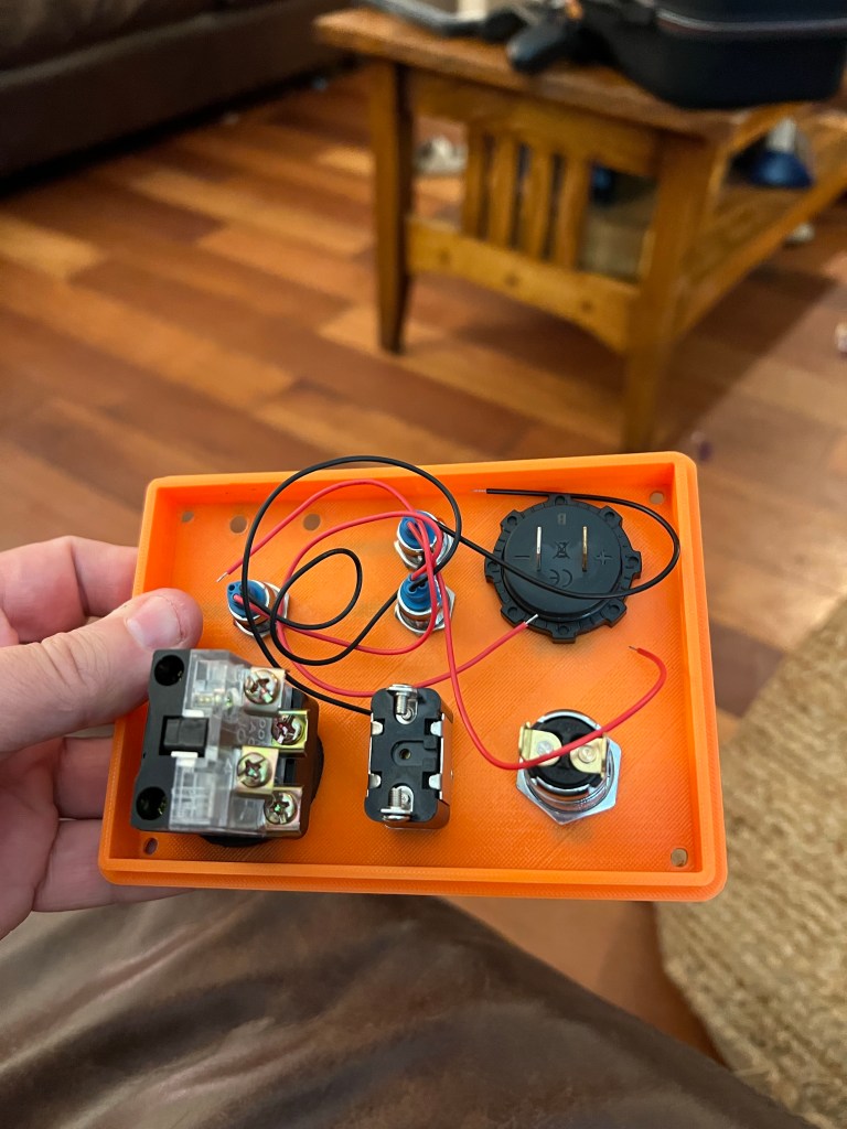
The whole controller is one series loop: battery → inline 5 A fuse → key switch → arm toggle → momentary fire button → igniter clips, and back to the battery. The continuity LED sits across the fire button: with the key on and the system armed, a tiny (~20 mA) current sneaks through the LED and the igniter to prove the circuit is complete. Press the fire button and the full battery current bypasses the LED and lights the igniter. The voltmeter and power LED sit across the battery so you can see pack health at a glance.
Bill of Materials (BOM)
This post contains Amazon affiliate links — as an Amazon Associate I earn from qualifying purchases, at no extra cost to you.
- 3D Printed enclosure (cover + base are my design) <- Download here
- Battery Enclosure (8 AA Batteries)
- 12V Battery Voltage display
- 3 Indicator LEDs (for power, continuity and armed status)
- On/Off Key Switch
- 1 red cover toggle switch
- 1 red push button switch
- 4mm banana plug female terminals
- 3” Metal Handles (Qty 2)
- Optional Swag: Launch Key Lanyard
- Inline mini blade fuse holder + fuse set (Nilight, 10 holders + 120 fuses including 5A) — the fuse holder goes on the battery + wire, with a 5A mini blade fuse in it. Blade fuses are time-delay by design, so the brief 6–10A surge when an igniter fires will not pop a 5A — but do not go smaller than 5A.
- Spare 5A mini blade fuses (Chanzon, UL listed, 10 pack) — cheap insurance in the range box.
- WAGO 221-413 lever nuts (bag of 10) — for the splices; much more reliable than twisted-and-taped joints.
- 18 AWG two-conductor silicone wire, pure copper (BNTECHGO, 50 ft) — for everything in the firing path (battery, switches, jacks). Thin or copper-clad-aluminum wire is part of how a reader melted a battery pack — use real copper.
Heads up: the 3D-printed enclosure is a paid download on Cults3D (a few dollars). Any project box from the hardware store works too — the wiring is exactly the same.



DIY MODEL ROCKET LAUNCHER CONTROLLER WIRING DIAGRAM

Updated August 2026 (rev B): the diagram now shows the inline 5 A mini-blade fuse and marks the three LEDs as 12 V panel-indicator modules. Two things the original diagram left implicit, made explicit: the LEDs in the parts list have built-in resistors — do not substitute bare LEDs (a bare LED in the continuity position would send ~10 A through the igniter the moment you turn the key), and the “1 Ω” element on the right is the igniter itself, not a resistor you buy. The continuity check passes a harmless ~20 mA through the igniter whenever the key is on — far below the no-fire current of standard Estes igniters (if you fly more sensitive e-match style igniters, unplug them until you are ready to arm).

These are utterly amazing! Are you planning to sell them, or release the .stl files and detailed part list? I know a lot of my friends would love them.
Any chance you’d publish a wiring diagram?
Updated to include wiring diagram.
I would like to build one of these to use when my son and grandson are visiting. My son and I launched rockets when he was young, and I’m continuing the tradition.
Might you be willing to share the STL for the case? I can print it on my own Prusa 3D printer.
Thanks!
Website updated with download link for the enclosure.
Thanks for uploading the 3mf file. I paid for it and downloaded it. It comes in as one object, and I don’t think it will print that way. Can you give me any advice?
The .stl object files you need are embedded inside the .3mf files. At least with PrusaSlicer, when you open the .3mf file, it gives you the option to import just the .stl files. Then you can slice and save the g-code for printing.
Tim — a very late reply, and an apology for it. Proximo’s answer below is right: the 3MF opens as one combined object in some slicers. In PrusaSlicer (or Bambu Studio), use File → Import and the cover and base come in as separate objects you can print individually. I’m adding print notes to the Cults3D listing so nobody else hits this. Thanks for buying the files, and again, sorry for the silence.
Can you elaborate on some of the current and voltage ratings of the components? What’s to prevent the lower current rated parts (like the key switch) from getting overloaded when a large current is provided to the igniter? And do the LEDs blow out easily? They can handle so little current.
Clayton — you were right to push on this, and it deserved a proper answer. The LEDs linked in the parts list are 12V panel-indicator modules with resistors built in (~20mA at 12V), so they handle it fine. The important warning — now in the updated diagram — is the reverse case: don’t substitute plain LEDs. A bare LED in the continuity position has nothing limiting current except the igniter itself, and that both destroys the LED and can fire the igniter the moment the key turns.
I dont know about rockets but in the mining world, the red cover toggle switch would be a second red button so that you have to push two buttons at the same time to initiate an explosion.
Matthew,
I found your launch system on line and decided to try building this myself, following your parts
With only the voltmeter and led light and key switch installed, I am melting the battery pack.
Thoughts on what would cause this???
The most likely cause of a melting battery pack is a short circuit or incorrect wiring somewhere in the system. If the wiring between the battery and the key switch, voltmeter, or LED is incorrect or if exposed wires are touching, this could create a direct connection to ground, leading to excessive current draw and overheating of the battery. Consider adding a 2A fuse. Add a fuse (1–2A) in series with the positive terminal of the battery to prevent overheating and protect against future short circuits. Test each component (key switch, LED, voltmeter) individually with a multimeter to ensure they are functioning correctly and not shorted.
Thank you!!!
Another question…the wire gauge size from the battery pack is 22.
Is using 18 gauge wire from some of the other components an issue ???
I am uncertain if mixing different sizes of wire creates problems with current flow…
Thoughts??
I think it should be fine.
Mark — closing the loop on this properly. Melting the pack with only the voltmeter, LED and key switch connected means battery current was flowing somewhere it shouldn’t: either a reversed voltmeter lead, an LED wired without realizing it must be the 12V type with a built-in resistor, or a pinched wire shorting to another terminal. I’ve updated the wiring diagram (rev B, now in the post) to make all of that explicit. One correction to my earlier advice: use a 5A mini-blade fuse, not 1–2A — firing an igniter pulls 6–10A for a fraction of a second, and a smaller fuse can blow before the igniter lights. The fuse is now in the diagram and the parts list. Sorry it took a melted pack to get this documented properly.